


Attitudes towards China plastic injection molding vary from person to person. If you’re looking for an affordable and customizable solution from a plastic manufacturer, look no further than Towpworks. Our package is designed to suit both start-ups and large companies, thus making it the perfect option for anyone looking to get into the plastics molding business. We offer a complete solution for the entire process: from design and 3D prototyping to mass production and delivery.
Towpworks Plastic Manufacturer’s injection molding design, mold creation, and mold planning are very critical to the plastics production process. The price of molds is often very high even for simple designs for some buyers. But we reduce the development cost and time of custom mold production because we have our own tooling shop that creates only our molds. In addition, we bundle individual orders for individual molds: you don’t need to start from scratch if you are working with us, an experienced plastics manufacturer.
Click Run to simulate a precision engineering injection molding cycle.


When to Use Injection Molding?
Injection molding is the ideal process for high-volume manufacturing of complex plastic parts. Although mold tooling costs are significant upfront, economies of scale drive the per-piece cost down rapidly as volumes increase — making it one of the most cost-competitive processes available for repeatable plastic parts.
Injection molding delivers precision and consistency that are difficult to match with other processes. A wide palette of resins and colorants offers exceptional design flexibility. Common application sectors include automotive components, household goods, medical devices, and consumer electronics.
Plastic Part Development Process
Drawing offices undertake a wide variety of work, depending on the industry in which they operate. When a potential client inquires about a project, stages are usually specified from the start to the end.
The purpose of the product will determine many activities associated with it. Vehicle manufacturers often subcontract many parts to specialists rather than manufacturing them themselves. Both the electrical and mechanical components must be regulated to ensure compliance with agreed-upon specifications.
Furthermore, the product must be flexible enough to be installed in specific locations and to operate under specific conditions. End users collaborate with component manufacturers to improve performance and quality.
Drawing and Design Process of Plastic Manufacturer
With the help of a Plastic Manufacturer, you can narrow down the options and make a smart decision. Clients often struggle to develop tangible ideas for specific products without assistance from a Plastic Manufacturer.
During the development process, the product design authority focuses attention on product specifications, including all requirements the product must accomplish, as well as the degree of configuration control. When designers seek advice in fields outside of their expertise — particularly where technology is at its forefront — expert consultation is essential.
Drawings at this stage should NOT be considered more than provisional. CAD (computer-aided design) is a very strong tool in primary design, as it helps in thinking through problems. Experts within the firm should contribute their ideas during this process to determine whether the solution is feasible.
Once a designer has finished crafting a design, he or she can share it with technical staff for suggestions and comments. The amount of configuration control applied during the early stages of the project is extremely important. It is necessary to document in some official format how decisions were made and why alternatives were not selected.
An organization’s commitment to quality goes beyond its technical capability to manufacture a satisfactory product and also encompasses financial aspects. The customer must approve the preliminary design concept after preliminary design work is completed. Product dimensions and operational parameters must be determined before spending money on further development.
Prototype of Plastic Manufacturer

You can build a prototype by testing the functionality of a specification so that you can be sure it’s operationally feasible without problems. As a result, some design changes may be necessary. Product tests cover all aspects of a product’s life cycle, including shock and vibration testing as well as testing under extreme conditions such as heat and humidity.
Once the prototype has been evaluated and performance targets confirmed, production drawing can begin. We will modify the prototype drawings for full-scale manufacturing processes during production. Making plans for loading and progressing work in the factory is necessary to ensure the plant is utilized as efficiently as possible.
The final product must be manufactured after the prototype is built. It is therefore necessary to keep specifications precise. Once the design of the equipment has been worked in its operational environment and its performance thoroughly evaluated, it can be released for full-scale production.
Plastic Manufacturer Structure Design (DFM)
Fast product delivery and on-budget production are two critical elements of manufacturing. Manufacturers and injection molders agree that Design for Manufacturability (DFM) has the most impact on production results. Mold flow analysis and prototype development can lead to significant cost and time efficiencies.
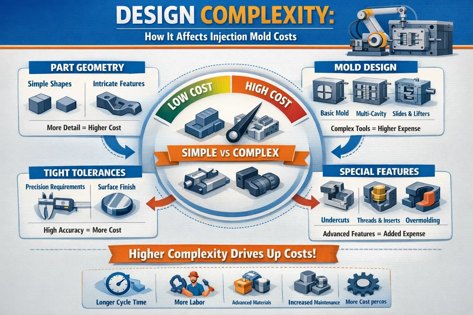
DFM involves several considerations to ensure that plastic parts are manufacturable from the outset. Key engineering parameters your molder will review include wall thickness uniformity, draft angles, rib geometry, and gate location. Early collaboration can uncover design changes that improve efficiency and reduce cost before tooling begins.
DFM Quick-Reference Parameters
| Design Feature | Recommended Value / Range | Notes |
|---|---|---|
| Wall thickness (general) | 0.8–3.0 mm | PP 1.2–3.0 mm; ABS 1.2–3.5 mm; PC 1.0–3.0 mm |
| Wall thickness variation | ±25% of nominal | Exceeding this causes differential shrinkage and warpage |
| Rib thickness | 40–60% of wall thickness | Use lower end (40%) to minimise sink marks |
| Rib height | ≤ 2.5–3 × wall thickness | Taller ribs increase ejection force requirements |
| Rib root fillet | R ≈ 0.25–0.4 × wall thickness | Reduces stress concentration |
| Draft — general outer surface | 0.5–1° | Minimum for smooth ejection |
| Draft — deep cavity inner surface | 1–2° | Increase with depth |
| Draft — textured / grain surface | 1–3° | Coarser texture requires larger angle |
| Draft — high-gloss / mirror | 0.25–0.5° | Requires excellent surface polish |
| Boss outer wall thickness | 40–60% of surrounding wall | Prevents sink marks at boss location |
| Inner fillet radius | R ≥ 0.25–0.5 × wall thickness | Larger radius for snap-fits and transparent parts |
| Cooling channel diameter | φ 8–14 mm | 8–10 mm for small/medium molds; 12–16 mm for large |
| Cooling channel centre-to-surface | 1.5–2 × channel diameter | Typically 15–20 mm for φ10 mm channels |
| Cooling channel centre-to-centre | 2–3 × channel diameter | Typically 40–60 mm |
| Sprue diameter | 4–8 mm (small/mid molds) | Large molds: 6–10 mm |
| Runner diameter | 4–7 mm (typical) | Slightly smaller than sprue |
| Pin gate diameter — small parts | 0.8–1.5 mm | GF-filled materials: increase by ~10% |
| Pin gate diameter — large parts | 1.5–2.5 mm | Adjust for viscosity of resin |
| Vent depth | 0.02–0.05 mm | Material-dependent; prevents diesel effect |

Plastic Manufacturer Injection Molding Process

The injection molding cycle consists of four phases: filling, compression/packing, holding pressure, and cooling. Each phase directly influences part quality, dimensional accuracy, and cycle time.
| Process Phase | Key Parameter | Typical Range |
|---|---|---|
| Filling | Injection pressure | 300–1,200 bar |
| Filling | Mold temperature (thermoplastics) | 10–120°C (up to 200°C for high-performance resins) |
| Holding pressure | Duration | Until gate freezes; process-dependent |
| Cooling | Share of total cycle | 50–70% of cycle time |
| Material shot utilisation | General resins | 20–80% of machine maximum shot |
| Material shot utilisation | Engineering resins | 30–50% of machine maximum shot |
| Cooling water temp vs. mold temp | Delta | 5–10°C below mold temperature |
| Cooling water flow rate (per circuit) | Typical | 15–30 L/min; Re ≥ 10,000 for turbulent flow |
| Mold temperature — ABS | Cavity temperature | 40–80°C |
| Mold temperature — PC | Cavity temperature | 80–110°C |
| Mold temperature — PP | Cavity temperature | 20–70°C |
| Mold temperature — PA 6/66 | Cavity temperature | 60–100°C |
Plastic Manufacturer Troubleshooting
Even with well-designed tooling, process defects can arise. The table below maps common defects to their root causes and first-line corrective actions.
| Defect | Likely Cause | First-Line Correction |
|---|---|---|
| Sink marks / voids | Wall or boss too thick; insufficient holding pressure | Reduce rib/boss thickness to 40–60% of wall; increase hold pressure and time |
| Short shot | Gate too small; excessive flow length | Open gate to 1.2–1.6 mm; add auxiliary gate for thin long-flow sections |
| Warpage | Wall thickness variation > ±25%; uneven cooling | Equalise wall thickness; balance cooling circuits; adjust holding pressure |
| Weld lines | Multiple melt fronts meeting at low temperature | Raise mold temperature; increase injection speed; vent at weld location |
| Sticking in cavity | Insufficient draft; excessive injection pressure | Add draft (min 0.5° on smooth surfaces); reduce injection-hold pressure |
| Flash | Clamping force too low; vents blocked | Check projected area vs. clamping force; clean vents; reduce injection pressure |
| Burn marks (diesel effect) | Trapped air in last-fill area | Add vents (0.02–0.05 mm depth) at fill extremities; reduce injection speed at end of fill |
Plastic Manufacturer Maintenance

Good quality parts depend on well-maintained molds. Like any precision tool, a mold begins to wear over time, and proactive maintenance is the most cost-effective way to protect that investment. Keeping a work log of all maintenance issues, as well as maintaining the tool periodically as it is used, is an easy and straightforward way to prevent problems.
Providing customers with guidelines regarding mold maintenance is the purpose of this guideline. Proper mold maintenance must be instituted and followed by customers.
Mold Steel Selection Quick-Reference
| Steel Grade | Type | Hardness (HRC) | Typical Application |
|---|---|---|---|
| P20 (1.2311) | Pre-hardened | 28–32 HRC | General structural molds, medium-volume production |
| 2738 | Pre-hardened (thick section) | 30–36 HRC | Large molds, heavy-section tooling |
| S136 | Stainless (corrosion-resistant) | 48–54 HRC (Q+T) | Mirror-polish, transparent parts, medical, food-grade |
| NAK80 | Age-hardening pre-hardened | 38–42 HRC | High-gloss, mirror finish, weld-repairable molds |
| H13 (1.2344) | Hot-work tool steel | 44–50 HRC (Q+T) | Hot runner zones, high-wear areas, glass-filled resins |
The Future of Injection Molding Industry
The global plastic injection molding market is expected to grow from 144,607 kilotons in 2023 to 177,464 kilotons by 2028, at a CAGR of 4.18% during the forecast period. Asia-Pacific dominates the market, with China, India, and Japan as the major consuming countries.
The major raw materials used for injection molding include polypropylene, acrylonitrile butadiene styrene (ABS), polystyrene, polyethylene, polyvinyl chloride (PVC), polycarbonate, polyamide, and other engineering resins. Application areas span packaging, building & construction, consumer goods, electronics, automotive, healthcare, and more.
Packaging is the dominant segment. Plastic injection molding offers a wide range of solutions in high-volume packaging, thin-wall containers, and bottle molds. It not only provides diversified packaging solutions but also reduces material consumption compared with alternative processes.
According to a report by the Packaging and Processing Technologies Institute (PMMI), the total value of the global packaging industry reached $422 billion in 2021. Growth is driven by population growth, rising disposable income in developing countries, and increasing demand for smart packaging solutions.
The U.S. remains a major player in the retail industry — five of the top ten largest retail companies in the world are headquartered in the U.S. According to the Flexible Packaging Association, flexible packaging is the second-largest packaging segment in the U.S. with a market share of around 20%.
Frequently Asked Questions
At what production volume does injection molding become cost-effective?
Industry experts put the profitability threshold at 3,000–10,000 pieces, depending on part complexity and mold cost. For simpler parts with lower-cost tooling, 3,000 pieces can justify injection molding. For complex multi-slide molds, 10,000+ pieces is a more realistic break-even. For very high-volume production (100,000+), injection molding typically delivers the lowest per-unit cost of any plastic forming process.
What is the typical mold temperature for common plastics?
Mold temperature varies significantly by resin. General guidance: PP 20–70°C; ABS 40–80°C; PC 80–110°C; PA 6/66 60–100°C. For high-performance resins such as PEI (Ultem) or PESU, temperatures of 140–190°C may be required. The correct mold temperature directly affects surface quality, residual stress, and part dimensional stability.
What wall thickness should I design for injection molded parts?
General recommendation is 0.8–3.0 mm for most commercial thermoplastics. More specifically: PP 1.2–3.0 mm; ABS 1.2–3.5 mm; PC 1.0–3.0 mm. Critically, wall thickness variation within a single part should be kept within ±25% of nominal thickness. Larger variations cause differential shrinkage, warpage, and sink marks.
How much draft angle is needed for injection molded parts?
Draft angle requirements depend on surface type. General outer surfaces: 0.5–1°. Deep cavity inner surfaces: 1–2°. Textured or grained surfaces: 1–3° (coarser textures need more draft). High-gloss mirror surfaces: 0.25–0.5°. Rib side faces: 0.5–1.5°. These are minimum values — adding more draft where geometry allows always improves ejection and mold life.
What does mold maintenance involve?
Routine mold maintenance includes cleaning parting surfaces and cavities after each production run, inspecting ejector pins and return springs for wear, checking cooling channel flow rates for blockage, verifying vent depths (0.02–0.05 mm) are clean, and lubricating sliding components. A maintenance log should document all interventions. Preventive maintenance is far less expensive than emergency repairs or mold replacement.
Ready to Start Your Injection Molding Project?
Send us your CAD files or product description — our engineers will review your design for manufacturability and provide a detailed quote within 24 hours.
Request a Free Quote →