






The Ultimate Guide to Simplifying the Design Process for New Product Developers
Creating a new product is both an exciting and daunting task. Whether you’re a seasoned designer or a new product developer, the journey from concept to production requires precision and a well-organized approach. The design process can be broken down into 10 key steps, each integral to ensuring your product is both functional and manufacturable. By understanding and following these steps, you can streamline your workflow and avoid costly mistakes along the way. Let’s explore these steps in detail.
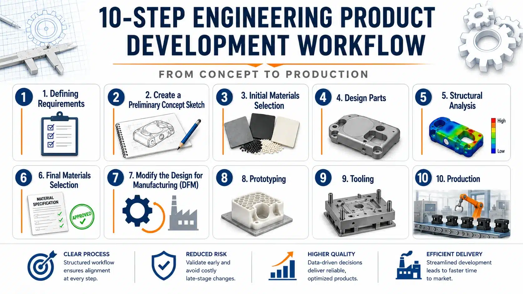
10-Step Product Development Workflow

Defining Requirements
Pin down function, load cases, operating environment, regulatory targets, volume and the cost ceiling before anything is drawn. Vague specs here turn into expensive rework at the tooling stage.
Copy & paste the code below. It embeds this workflow on your site and includes a small credit link back to us.
1. Defining Requirements
The first and most crucial step in any design project is defining the requirements. This stage involves determining the product’s primary function, target market, and user needs. A detailed set of requirements guides the design process and keeps everyone on the same page.
For example, when designing a new consumer electronics product, you might consider factors such as size, weight, and battery life. The more specific you are, the easier it will be to align your design decisions with the goals of the product. It’s important to keep an open line of communication with all stakeholders, as their feedback can help refine the product vision and define features that will differentiate the product in the market. Many developers refer to a report investment process to better manage early-stage expectations.
2. Create a Preliminary Concept Sketch

Once you’ve defined the product requirements, it’s time to start thinking visually. Creating a preliminary concept sketch is often the first step in the design phase. At this stage, your sketch doesn’t need to be precise—just a rough representation that helps communicate your vision. This sketch acts as a tool for identifying potential issues early on. For deeper insights into the ideation stage, check out our guide on concept to mass production.
For example, if you’re designing a housing unit for an electronic device, a rough sketch can highlight whether the internal components will fit together and whether there’s sufficient space for heat dissipation. The sketch helps you catch problems that might not be obvious in abstract descriptions. Once the concept is solid, it can lead to more detailed designs and 3D modeling.
3. Initial Materials Selection
At this stage, you need to consider the materials you’ll use in the final product. Materials selection is essential not only for functionality and durability but also for manufacturability. Different materials offer various benefits, such as strength, flexibility, resistance to heat, and ease of molding. You can learn more about thermoplastic properties from authority resources like Wikipedia.
If you’re designing a product with a plastic casing, for instance, you’ll likely use injection-moldable thermoplastics like ABS (Acrylonitrile Butadiene Styrene) or polycarbonate. ABS is often chosen for its strength, impact resistance, and ease of injection molding, which makes it ideal for consumer electronics housings. Understanding material properties helps inform your design decisions—how thick should walls be? Will the material be able to withstand repeated use? These questions guide your decisions early in the design process.
| Material Name | Abbr. | Common Applications |
|---|---|---|
| General Purpose Polystyrene | PS | Lampshade, instrument housing, toys, etc. |
| Teflon, PFA | Teflon/PFA | Chemical fittings, mechanical parts |
| ETFE | ETFE | Chemical fittings, mechanical parts |
| Acrylonitrile Butadiene Styrene | ABS | Instrument housing, House ware, advanced toys |
| Acrylonitrile Styrene | AS(SAN) | Daily transparent containers |
| Acrylonitrile Styrene acrylate | ASA | Outdoor furniture, car outer mirror housing |
| Butadiene Styrene | BS(BDS) | Special packaging, food containers, pen |
| Cellulose Acetate | CA | Tool handles, containers, etc. |
| Cellulose Nitrate | CN | Spectacle frames, toys, etc. |
| Chlorinated Polyethers | PENTON | Substitute for stainless steel |
| Chlorinated Polyethylene | CPE | Building materials, pipe, cable insulation |
| Chlorinated Polypropylene | PPC | Daily necessities, electrical appliances |
| Ethyl Cellulose | EC | Tool handle, sports goods, etc. |
| Ethylene-Propylene Copolymer | FFP | Radar insulation, high frequency instruments |
| Ethylene-Vinyl Acetate | EVA | Soles, film, daily necessities |
| High Density Polyethylene | HDPE | Packaging, buckets, toys |
| High Impact Polystyrene | HIPS | House ware, electrical components |
| Low Density Polyethylene | LDPE | Packaging bags, plastic flowers, wire |
| Methyl Methacrylate-Butadiene | MMB | Machine frame, daily necessities |
| Poly(Butylene Terephthalare) | PBT | Electronic connectors, automotive parts |
| Poly(Ethylene Terephthalare) | PET | Bearings, chains, gears, tapes, etc. |
| Poly(Vinyl Chloride) | PVC | Pipe, wire insulation, sealing, etc. |
| Polyamide-1010 | PA-1010 | Rope, pipe, gear, mechanical parts |
| Polyamide-6 | PA-6 | Bearings, gears, tubing, daily necessities |
| Polyamide-66 | PA-66 | Machinery, automobile, electrical equipment |
| Polyamide-9 | PA-9 | Mechanical parts, pump, cable jacket |
| Polycarbonate | PC | Transparent parts, resistance to impact parts |
| Polychlorctrifluoreethylene | PCTFE | Transparent mirror, valve fittings |
| Polyethersulfone | PES | Electrical, aircraft and automotive parts |
| Polymethyl Methacrylate | PMMA | Lampshade, windshield, instrument case |
| Polymethyl Methacrylate-Styrene | MMS | Transparent products with heavy loading |
| Polyoxymethylene (POM) | POM | Abrasion resistance, mechanical gear, bearings |
| Polypropylene | PP | Packing bag, packaging, daily necessities |
| Polysulfone | PSU(PSF) | Electrical parts, aircraft parts |
| Polytetrafluoroethylene | PTFE | Radar insulation, high frequency components |
4. Design Parts
With your material selection in hand, it’s time to design the parts that will make up your product. This step is crucial because each material behaves differently. The way a thermoplastic like polyethylene expands when heated is quite different from how metals behave. Utilizing a design principles for plastic parts framework is highly recommended here.

In injection molding, for example, the design needs to account for the material’s shrinkage during cooling. If you don’t account for this, you could end up with warped or misshapen parts. A good practice is to include features like draft angles in your design, which help with easy removal of the part from the mold. The more you align the design with the material properties, the easier and more cost-effective the manufacturing process will be.
5. Structural Analysis
Design for Injection Molding
Eight checks that decide whether your part molds clean, or fights the tool for its whole life.
Wall thickness rules the whole job
Wall thickness sets cycle time, sink marks, warpage and fill pressure. Cooling time rises with the square of the wall. Double the wall and you roughly quadruple the time the part sits in the tool.
The second rule matters just as much: keep the wall uniform. Plastic shrinks as it cools. A thick zone cools last, keeps shrinking after the gate freezes, and pulls the surface in. That is a sink mark. If the skin is stiff enough to resist, the shrinkage tears a void inside instead.
Hold the nominal wall within ±10% across the part. Where a change is unavoidable, keep the step under 25% of the nominal wall and blend it over a length of at least 3× wall. Never step the wall with a square shoulder.
Cooling time is a first-order estimate from the one-dimensional plate solution. It ignores gate freeze-off, hot runner effects and mold cooling layout. Treat it as a comparison tool, not a quote.
Stiffness comes from ribs, not from thicker walls
Bending stiffness scales with height cubed. A rib 3× the wall height adds far more stiffness than doubling the wall, and it costs almost nothing in cycle time. This is the single highest-value move in plastic part design.
The catch is the rib root. Where the rib meets the wall, material mass builds up. That local thick spot cools last and pulls a sink mark onto the show surface directly opposite the rib.
Base thickness 0.5–0.6× wall for amorphous resins, 0.4–0.5× for high-shrink semi-crystallines. Height up to 3× wall. Draft 0.5–1.5° per side. Root radius 0.25–0.5× wall. Spacing at least 2× wall so the steel between ribs still cools.
Three fixes, in order of cost: move the rib off the show face, break the opposite face with a texture or a styling groove, or core out the wall behind the rib so the mass balances. Adding hold pressure only hides small sinks and often adds stress instead.
Draft is what lets the part leave the steel
A molded part shrinks onto the core. Ejector pins then push it off. With no taper, the part drags the full depth of the core and picks up scuff lines, stress whitening or a torn wall. Draft turns that sliding contact into an instant release.
Texture makes it worse. A grained surface is a field of tiny undercuts. Every 0.025 mm of texture depth needs roughly 1.5° of extra draft on top of the base requirement.
0.5° is the practical floor for a polished vertical face. 1–2° is the normal default. 3° suits a light grain, 5° and up a coarse one. Deep ribs and tall cores want at least 0.5° per side even when the drawing says the face is critical. Shut-off faces and sealing surfaces are the exception, and they need a written agreement before steel is cut.
Sharp inside corners are stress risers
A sharp internal corner concentrates stress, blocks flow and creates a local hot spot in the steel. It is also the place parts break first in drop tests. Adding a radius is free at the design stage and expensive after the tool is cut.
The chart below is the classic stress-concentration curve. Below R/T = 0.3 the factor climbs steeply. Above R/T = 0.6 you gain almost nothing, and you start adding mass that sinks.
Outside radius = inside radius + wall thickness. Do that and the material thickness through the corner stays equal to the nominal wall. Use the same inside radius everywhere so the polisher runs one ball cutter, not five.
Bosses: strong enough to hold a screw, thin enough not to sink
A boss is a rib rolled into a tube. Every rib rule still applies, plus two more. The wall of the boss has to stay thin relative to the nominal wall, and the boss must not sit directly against a side wall, or the two masses merge into one thick lump.
Core the boss from the parting line so the wall stays even. Give the core 0.25–0.5° draft, or it will not release. Stand the boss off the side wall by at least one wall thickness and tie it back with a gusset. Keep thread engagement at 2–2.5× the screw diameter, and add a counterbore at the mouth so the screw starts straight and the top of the boss does not split.
Every undercut buys a moving part in the tool
The cheapest mold opens in one direction and the part falls out. Anything that traps the part needs a slide, a lifter, a collapsible core or an unscrewing unit. Each one adds cost, adds cycle time, adds a witness line on the part, and adds something that can fail at 200,000 shots.
Pick the features your part actually needs. The panel adds up what they do to the tool.
Many undercuts disappear with a small change. Add a pass-through hole in the opposite face so a core pin can form the feature on straight pull. Move the parting line onto a styling break. Split one part into two and weld or clip them. Turn a rigid snap into a shallow bump-off that a flexible resin can strip over. Each of these is worth an hour of CAD work before the RFQ.
The gate decides where the weak lines land
Melt enters at the gate and races outward. Where two flow fronts meet, they form a weld line. That line can be 20–60% weaker than the bulk material, and on a glass-filled resin it is worse, because the fibers lie parallel to the line instead of across it.
Click anywhere in the plate to move the gate and watch the fill pattern change. Openings split the flow and put a weld line downstream of every hole.
Click the plate to place the gate.
Choosing a gate type
| Gate | Auto de-gate | Vestige | Best for | Watch out for |
|---|---|---|---|---|
| Edge / side | No | Trimmed nub | Flat parts, most tooling | Manual trim adds labor |
| Submarine (tunnel) | Yes | Pin mark, hidden | Small to medium parts | High shear, not for filled or brittle resins |
| Hot tip / valve gate | Yes | Small dimple or flat | Cosmetic parts, no runner scrap | Highest tool cost, needs controller |
| Direct sprue | No | Large scar | Thick single-cavity parts | Sink under the gate, long cooling |
| Fan | No | Wide trimmed edge | Wide flat panels, low warp | Needs trim fixture |
| Diaphragm | No | Ring on the bore | Round parts needing concentricity | Secondary machining |
Where can a gate vestige be accepted? Which surface is cosmetic, so the weld line must be moved off it? Is the longest flow path within reach for this resin at this wall? Answer those and the filling analysis usually confirms what you already chose.
Shrinkage first, tolerance second
The cavity is cut larger than the part. How much larger depends on the resin, the wall, the hold pressure and the direction of flow. Semi-crystalline resins shrink two to four times more than amorphous ones, and glass fiber makes shrinkage directional.
That is why a tolerance that is routine in aluminum can be impossible in PP. Ask for tight numbers only where the function needs them, and say which datum they are measured from.
Hold pressure and hold time change shrinkage more than any other setting. Mold temperature comes next, then wall thickness. A part measured hot off the press is not the part you get 48 hours later, especially in PA and POM. Set your inspection window and write it on the drawing.
Values shown follow the general shape of the SPI and DIN 16742 guidance for standard and fine tolerance grades. Use them to sanity-check a drawing early. A final capability statement comes from the mold flow study and the first-article report.
Self-check
Eight questions from the sections above. Answers explain themselves as you go.
Structural analysis is one of the most critical steps in the design process. Without it, your product may end up failing under real-world conditions, which could lead to costly recalls, delays, or even a damaged brand reputation. The goal here is to predict and analyze how the product will behave when subjected to various forces, environmental conditions, and stresses. For complex geometry, Finite Element Analysis (FEA) is the industry standard for verification.
For example, when designing an injection-molded plastic component, the material’s structural integrity is paramount. Certain materials, like polypropylene (PP), might behave differently under stress compared to materials like polycarbonate (PC), which is much more rigid and durable. Using Finite Element Analysis (FEA) software, engineers can simulate how the part will respond to pressure, temperature changes, and mechanical forces. FEA helps identify weak spots in your design, such as potential points of failure or areas prone to warping under heat or stress. This analysis is especially important for products that will be subjected to heavy usage or extreme conditions, such as automotive parts or outdoor electronics.
Additionally, in injection molding, designers must consider the cooling and shrinkage of materials. If the design isn’t properly aligned with how materials contract during cooling, the product may experience dimensional inconsistencies, warping, or cracking. For example, parts with thick cross-sections may cool at different rates, causing stress that could lead to failure over time. By conducting a structural analysis, you can mitigate these risks, ensuring that your product is robust and reliable in the long term.
6. Final Materials Selection
As your design evolves, it’s time to finalize your materials selection. By now, you should have a clearer understanding of which material best fits your product’s needs in terms of cost, performance, and manufacturability. This decision may come after further testing, simulation, or consultation with suppliers. For help determining costs, you can use our smart injection mold cost calculator.
For example, if you’re designing a medical device that requires sterilization, you might opt for a material like PEEK (Polyether Ether Ketone), which is known for its excellent resistance to heat and chemicals. On the other hand, if you’re designing a disposable packaging product, something more cost-effective like PET (Polyethylene Terephthalate) might be suitable.
7. Modify the Design for Manufacturing (DFM)
Design for Manufacturing (DFM) is the process of refining your design to make it easier, more cost-effective, and more efficient to manufacture. It’s an essential step for anyone looking to move from prototype to production, as it helps ensure that the product can be made without significant delays or unexpected costs. Reviewing DFM best practices can significantly shorten your timeline.
The DFM process involves analyzing every aspect of the design to identify potential challenges that could arise during production. In the case of injection molding, this might involve simplifying parts to reduce the complexity of the mold. For example, if the design has deep undercuts or complex geometries that make it difficult to eject the part from the mold, these features could be modified or eliminated altogether.
A good example of DFM in injection molding would be the use of draft angles. Without draft angles (slight slopes on the sides of the mold cavity), the molded part might get stuck in the mold, requiring additional labor or tooling to remove it. Draft angles of about 1 to 2 degrees are often used to facilitate easy ejection. In addition to draft angles, gate and runner systems (which direct the flow of molten material into the mold) are also optimized during the DFM process. By strategically placing the gates and ensuring a uniform flow of material, manufacturers can reduce cycle times and material waste, which in turn lowers production costs.
Another important DFM consideration is part count. The fewer parts a product has, the easier and less expensive it is to manufacture. Consolidating components, where possible, or designing for multi-functional parts can help reduce manufacturing time, tooling complexity, and assembly costs. Ultimately, DFM is about striking the right balance between design complexity, manufacturability, and cost efficiency.
8. Prototyping
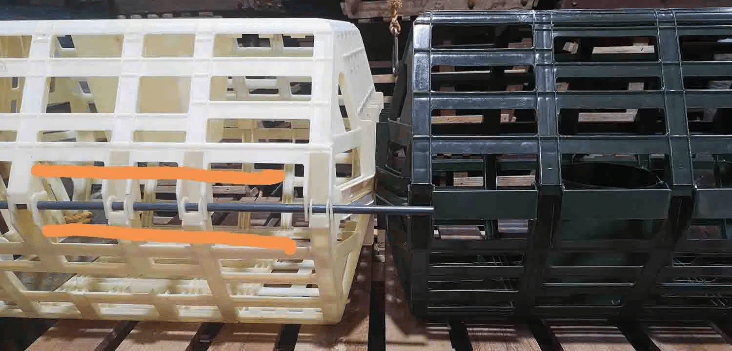
Prototyping is where the rubber meets the road. Until this stage, your design exists only as an idea or a digital file. The prototype is the first time you’ll see and feel your design in the real world. It’s an invaluable step for identifying issues that may not have been apparent during the design phase and for verifying that your design works as intended before moving into full-scale production. For early-stage testing, many start with prototyping advice for beginners.
For injection-molded products, prototyping often involves creating a limited-run mold that’s used to produce a small batch of parts. These parts are then tested for functionality, fit, and finish. This stage provides a chance to evaluate the product’s real-world performance, including its strength, ease of assembly, and user experience. If you’re working on a consumer product, like a new mobile phone case, you may also want to test for tactile qualities—how does the product feel in hand? Is it too bulky, too slick, or uncomfortable to use?
In some cases, rapid prototyping methods like 3D printing are used to create a prototype. While 3D printed prototypes can help visualize the form and fit of a design quickly, they typically don’t replicate the material properties or production processes of injection molding. However, 3D printed models can provide invaluable insights into design adjustments that are necessary before creating more expensive molds.
Prototyping also offers the opportunity to refine the assembly process. Can all parts be easily assembled? Is there an easier way to connect them? Are any adjustments needed in terms of part tolerances? Testing with a prototype helps uncover these small but significant issues that might lead to bigger problems during mass production.
9. Tooling
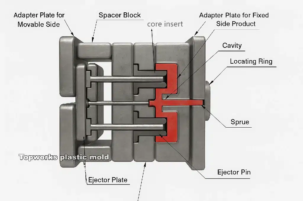
Tooling is arguably one of the most expensive and time-consuming stages of product development. This step involves creating the molds or tools that will be used to produce your product in large quantities. The tooling process involves crafting precise molds for injection molding, die casting, or other manufacturing techniques, and it sets the stage for mass production.
Creating the right tooling is essential to the success of your product’s manufacturing process. If the tooling is inaccurate or poorly designed, it could lead to defects such as poor surface finish, dimensional inaccuracies, or excessive cycle times. For injection molding, the creation of the mold is a highly specialized task that requires experienced engineers and machinists. The mold design process considers the number of cavities (how many identical parts can be produced at once), gating systems (how the molten material enters the mold), and cooling channels (to control the temperature and ensure uniform cooling).
The tooling process often begins with prototyping the mold itself, creating test molds to verify the design and identify any issues before full-scale production begins. Once the mold is ready, it undergoes testing to ensure that it’s capable of producing consistent, high-quality parts without excessive wear. For example, if you’re designing a component for an automotive application, you’ll need tooling that can handle high volumes without degradation of precision. Typically, this tooling is made from hardened steel to withstand the pressure of multiple injection cycles.
It’s important to note that tooling costs are a significant part of the overall manufacturing cost, and these costs can vary depending on the complexity of the product design. Complex features, like multi-cavity molds, may cost more to produce but result in faster cycle times and lower per-unit costs. Additionally, if the tooling is designed poorly or needs frequent maintenance, it could lead to delays in production or increased scrap rates, which ultimately raises the cost of production.
10. Production
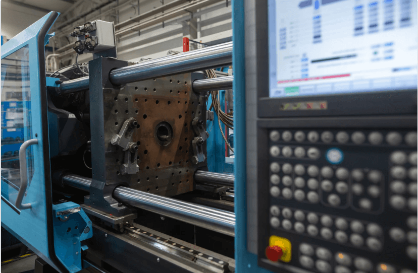
Finally, we arrive at the production phase, where your product comes to life in large quantities. During production, quality control is key. For injection molded parts, this means checking each batch for defects such as short shots (incomplete filling), warping, or sink marks (surface imperfections due to cooling).
At this point, you’ll likely enter into a continuous feedback loop with the manufacturing team, ensuring the process stays on track. If you’ve followed all the previous steps carefully, the production phase should run smoothly. But even then, regular monitoring is essential to maintain the quality and integrity of each batch. For more information on operational standards, visit our blog for daily updates.
In conclusion, successful product development is a journey that requires meticulous planning and careful execution. From defining your requirements to final production, each step in the design process plays a critical role in ensuring your product not only meets customer needs but is also manufacturable and cost-effective. By following these 10 key steps, you’ll set yourself up for success and avoid common pitfalls that can derail product development. Take each step seriously, and you’ll be well on your way to turning your ideas into reality.
