A reasonable and optimal molded part structure design can not only simplify plastic injection mold manufacture, reduce the cost of the mold, but also to simplify its molding process to improve the good quality rate of products.
Before the design of plastic parts, designer should learn about the function, environmental conditions and loading conditions (including dynamic and static load), understand relations between different parts and the effect of the assembly. Plastic parts function should be accurate and detailed possible, the more comprehensive the plastic parts design is, the better the design of the plastic parts can meet the requirements.
[tabs history=”true”]
[tab title=”Radii” anchor=”Radii”]
Radii
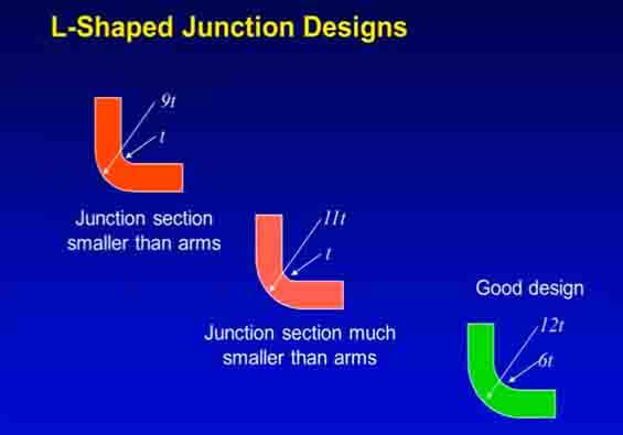
There are two main causes for plastic part failure: molded-in notches, and sharp internal corners. These are largely caused by designers failing to provide the part with a sufficient internal radius to avoid the issue. When radii are noted on drawings, they are often inadequately small, and their importance in high-stress areas is neglected.
In reality, internal corners require a carefully specified radius, to help cut down on stress concentrations at these essential areas. If the corner is too sharp, then the force factors at this point can be tripled or even quadrupled. For that reason, it is recommended that a fillet or radius of 0.5-0.6 times the wall thickness is incorporated at these points. Such parts will allow one to reduce stress on radiused corners compared to sharp, nonradiused sections.
It should be noted that materials with poor elongation qualities are highly susceptible to cracking under external and internal forces- for instance, a boss where a screen expands its outer diameter during assembly.
It is also necessary to specify radii on exterior corners of certain parts where a square-cornered shaft will need to fit into a plastic part. Examples of these parts include pulleys and gears. Putting radii on external corners has many benefits, from sink and stress reduction, to assisting with material glow. Put simply, the larger the radius, the more impact load that section will be able to absorb.
For instance, some designs will require a sharp, 90-degree corner. If the part is subjected to impact, then radii are essential to absorb the energy at the corners, and reinforce the ribs of the part. However, radii can have a negative impact on the appearance of parts, as well as their ease of packaging. If the radii become too big for these factors, then the designer may wish to solve the problem by opting for an impact-modified material in the manufacturing process.
Under test conditions, when the radius is increased, parts are able to absorb more energy before failing, and in many cases failure is averted entirely. Impact tests to external corners show that energy absorption can be increased up to five times by incorporating larger, more rounded corners- and at the top of the part, this increase can be as much as ten times. On the other hand, if ribs are added to make the part stiffer, they can have a negative impact on the part’s ability to absorb energy, since the walls cannot deflect.
If the rib section is properly designed, though, and an impact-modified resin is used, then even a part which was otherwise problematic may work well in practice. For instance, polycarbonate is extremely good at absorbing energy, and when coupled with a larger radius, means the part will be able to absorb a lot more energy before failing.
To gain a better understanding of why thermoplastic materials behave the way they do, and why some are naturally stronger than others, it is necessary to understand how they behave under standardized ASTM testing of physical properties. All plastics demonstrate a similar stress/strain curve, where failure occurs at or close to the top of the curve (although this will vary depending on filler and reinforcements). Filled or reinforced resins come with a lower elongation- some 10% or under- meaning they are less able to absorb or deflect energy upon impact. This means they need a larger radii to cut down stress concentrations when they are faced with loads or impacts.
In the case of short or long glass-reinforced resins,this rule often comes under question when data sheet values are examined. In these cases, the data would seem to suggest that more highly reinforced resins have an increased impact value. In truth, though, this is down to the effect of the glass fiber/resin matrix strength at the notch; it does not reflect the absorbing value of the base resin itself. With a higher glass loading, a greater radius is needed to make the part tougher.
[/tab]
[tab title=”wall thickness” anchor=”wall thickness”]
Nonuniform Part Thickness
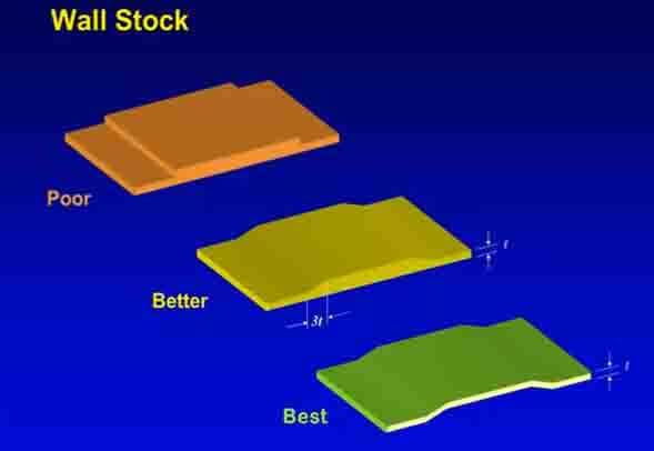
After insufficient radii, the next leading cause of plastic part failure is nonuniform wall thickness. This can cause wider tolerances, warpage, voids and sinks, a poor fill due to pressure drops, and stresses which are molded-in. All of these issues are down to bad part design, which stops the resin from being able to fully pack out during the molding process. If uniform sections are used, then these can all be avoided.
Molded-in part stresses are often caused by a combination of thick and thin sections. When the part cools, this leads to different shrinkages. Since the thicker section holds more heat, this can lead to all manner of issues such as sinks, voids, and warpage.
It can also lead to flow problems around corners, since it encourages pressure drops and dead pressure flow areas. If nonuniform section thickness is used, and thin part sections feed thicker sections, the pressure will drop in the thicker section. That may mean that the part is not sufficiently filled. On top of this, the thin section could become over-packed when trying to fill the thicker section.
Designers will therefore need to transition and core out thick sections, to make the part thickness as uniform as it can be. Not only does this reduce these internal sinks and voids, but it also makes the part stronger, and saves on wasted materials.
Uniform wall thickness should therefore a key part of design, and parts should be gated into the thickest section to ensure an even packout. Since material waste costs money, this should be the aim of all manufacturers, and it also cuts down on quality issues further down the line. Plastic parts will need to be cored out to the maximum to better utilize material, as well as minimizing the risk of part stress and warpage. If extra strength or rigidity are needed, then ribs are to be used.
[/tab]
[tab title=”ribs” anchor=”ribs”]
Ribs for Strength and Quality
Where added part strength and rigidity are necessary, then thinner rib sections make for better designs. Multiple smaller ribs, or a single large yet thin rib, are more effective than one large, thick rib. This can be demonstrated by calculating the stiffening effects of each option. In the case of thinner rib sections, molding and part problems are cut, and the part gains additional impact resistance because molded-in stresses in these areas are lowered.
Designers should therefore use moment of inertia calculations to come up with a rib design that reduces the risk of part problems whilst simultaneously strengthening the part. An effective design will use the plastic material in the optimum proportions to maximize the results. Proper rib design also sidesteps molding problems, and therefore gives a faster molding cycle with less quality control issues.
It is also important to note that color variation will occur in thick and thin sections. With a thicker section, the color will appear more vibrant and intense. This is especially noticeable when using translucent colors, and with certain types of resins depending on the section thickness.
[/tab]
[tab title=”Weld-Line” anchor=”Weld-Line”]
Weld-Line Considerations
Wherever the material is required to flow around an obstacle, hole, boss, or cutout, a weld-line will be formed, at the point that multiple melt flows meet. If this weld-line forms at a high stress point, then this may present a big problem to the integrity of the part.
Designers will need to make a note of high-stress areas on the part, allowing the mold designer to carefully select the best gate location for the part. The issue is often only noticed when part failure occurs, but through careful planning of cavity layout and gate location, it can usually be averted. So long as potential weld-line issues are known in advance, then there are several ways that those issues can be minimized.
Shifting the gate location, or working to minimize the weld-line effect at these obstructions are both valid options. Another option is multiple gating, which will naturally shift the point at which the melt fronts meet and the weld-line is formed.
One way to strengthen weld-lines at the very edge of a part is to use flow tabs, which will be removed later in the process. These tabs are typically used at the points where weld-lines form, to help the melt fronts to flow together smoothly. To use them, though, the mold cavity at this point needs to be suitably vented, or the air in the cavity will prevent a smooth meeting.
Excess air could slow down the melt fronts, and cause bubbles to form. Should the air not be vented fast enough, then it could well cool the melt fronts so that they don’t bond properly, creating a significantly weakened melt-front. To solve this issue, extra localized heating is often used on weld-lines to ensure the melt fronts come together nicely.
Weld-lines should be avoided in parts that require holes, and there are a range of methods to do this- especially if the lines occur at high stress points. The holes may be marked for drilling later in a secondary operation. Where countersunk bind holes are needed, at least lA of the section thickness should be retained. This will allow the material flow to minimize the weld-line formation opposite the hole. Where blind holes are concerned, the minimum thickness of the bottom should be at least ]/6 diameter. With reinforced materials, the part’s weld-line strength can be calculated by using the parent resin,s strength.
The reason for this is that reinforcements such as glass fibers will not flow over the weld-line to link with the opposing melt front. Even when using an external flow tab, reinforcement interflow is unlikely until the fronts are suitably far away from any obstruction. In the case of some part designs, the weld-lines may well be highly visible. For instance, using colors or reinforced materials means noticeable surface variations will occur at he knit line.
To increase weld-line strength, the melt temperature of the resin may be raised, or the mold itself heated. There are usually more issues with weld-line strength when using amorphous resins, since they have a lower softening temperature and higher melt viscosity. Crystalline resins,which have a sharper melting point,may cool and freeze off faster, leading to a weak weld-line joint. Using flow tabs with adequate venting,increased melt temperature, localized cavity heating, and hotter mold temperatures can limit these weld-line effects, and thereby improve joint strength.
[/tab]
[tab title=”5″ anchor=”55″] 5555555555555 [/tab] [tab title=”6″ anchor=”66″] 6666666666 [/tab] [tab title=”7″ anchor=”77″] 77777777 [/tab] [tab title=”8″ anchor=”88″] 88888888888888 [/tab] [/tabs]
[divider_top]
Tolerances:
A high degree of accuracy in molded parts is expensive to achieve. On small tolerances as close as -0.002 in. are possible.size is increased to & few inches, over-all tolerances increase to approximately ±0.005 in. On large pieces, tolerances of about 土0.001 to 0.002 in. per in. are obtainable. Tolerances closer than actually mandatory should not be specified; as specified accuracy increases, cost increases disproportionately.
Though it is difficult to generalize about design factors for injection, compression and transfer moldings, the following design rules. should be considered:
- Use sufficient draft on long thin shapes to permit their withdrawal from the mold.
- Minimize coring. When cores are used they should be easy to withdraw.
- Avoid internal and external undercuts; they make withdrawal of parts difficult and require considerably more expensive molds.
- Provide ample fillets on inside comers, and avoid sharp external edges and comers except at the parting line of the die.
- Avoid large flat areas. Dappling or otherwise breaking up the surface is recommended.
- Keep tolerances as liberal as possible. Excessively close tolerances add to cost because of increased die costs and high rejection rate.
- Avoid abrupt changes in wall thickness.
- Locate parting lines so that flash can be removed easily without marring surrounding areas.
- Locate holes for easy coring.
- Use ribs to achieve desired strength and stiffness. Ribs permit materials savings by reducing section thickness.
- Use inserts for threaded holes where high stresses are anticipated or where considerable wear is to be encountered. Round inserts are preferred.


